Last post we left off on the beginnings of the lower control arm and what it takes to get to the point of designing the part. At this time, we had not considered the exact design goals of the LCA beyond it should be lighter than OEM and nearly every other unit on the market.
We’d like to take this time to discuss the necessity to have design goals as it may be something you have not dealt with if you are not in the engineering world. Also, this was one of our first

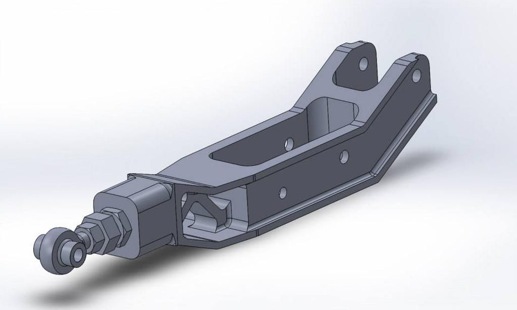
One of the first designs. This one would end up not meeting some of the design criteria.
What goals ended up shaping our LCA?
Weight: Lighter than the OEM and other aftermarket units. This helped us determine which material to use.
Packaging: We wanted our LCA to retain OEM mounting points. This allows the LCA to be used on a stock suspension set-up, as well as coil-overs, and not lower the rear of the vehicle like other units geared more towards stance. This is what ruled out the above design.
Affordability: We knew to start out the LCA would have to be priced competitively to do well in the market. After a little market research, it appeared $600 retail would be our goal for the project. This also helped us determine which material to use as it ruled out cost prohibitive ones.
Manufacturing: We decided early on that we wanted a machined component. With a cut, bent, and welded steel unit, tolerances are looser and heavily dependent on the shop doing the work. On the other hand, a modern CNC machine can hit tolerances tighter than 0.005″ without breaking a sweat.
Strength: We knew we wanted
Appearance: We all want a part that looks great and performs even better. Looks are definitely important and it needed to have a certain sex appeal.
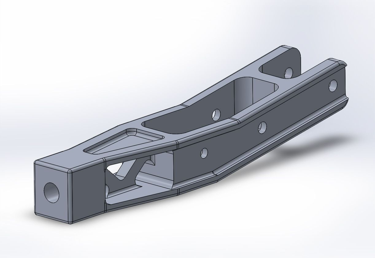
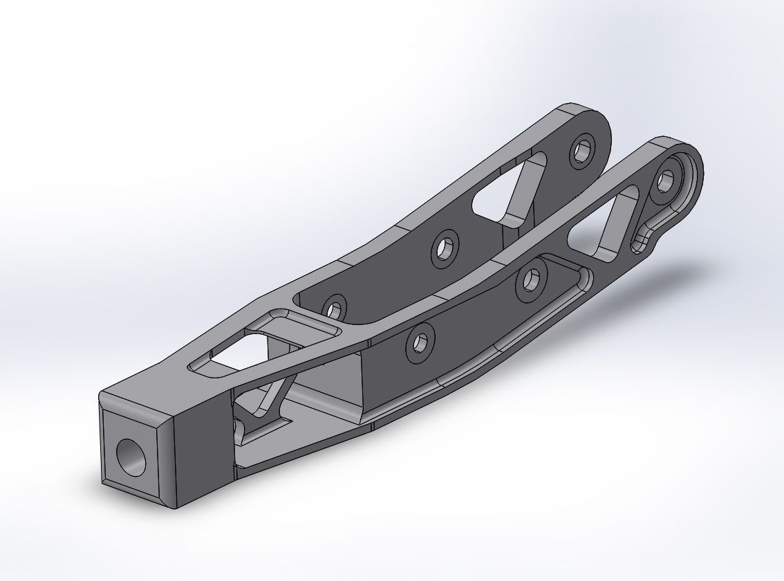
With those design goals in mind, we were able to narrow down our approach and start designing different LCA’s. Yes, multiple, as the first design is rarely the design to pursue further. The design process starts with the four LCA points, the inboard point, the ARB point, the damper point, and the outboard knuckle. From there, it is simply connecting these points in a logical fashion to keep deflection to a minimum and reduce stress concentrations. With a bit of mechanical


Design #3 and #4 were getting closer to something we liked visually but the

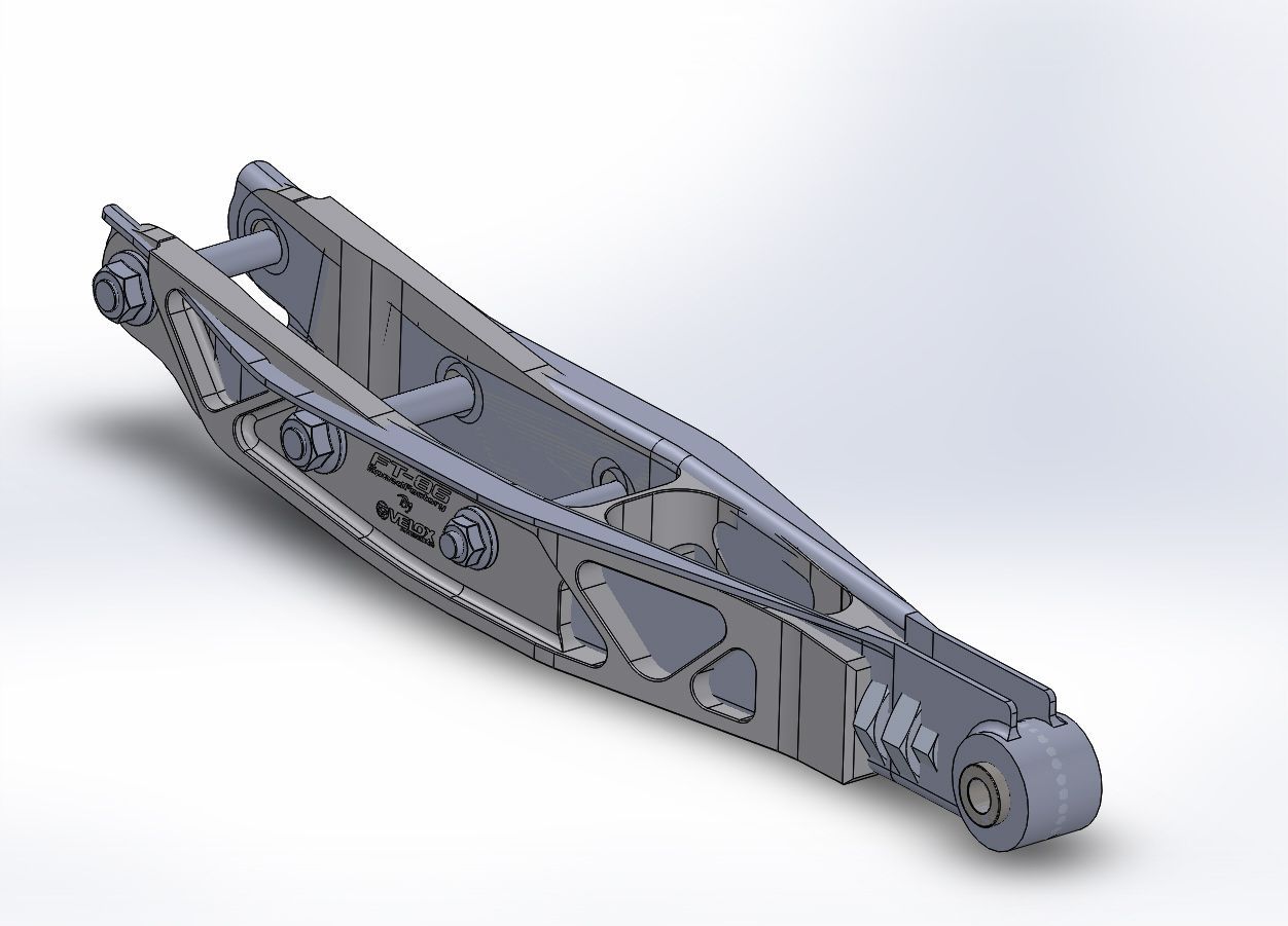
Each LCA was designed with the factory LCA model in the assembly. This ensures all important points are maintained. This one
FT-86 Lower Control Arm Development