Now that we have prototypes in hand, we were able to test the units with real-world loading conditions. Why would this be necessary you ask? Well, oftentimes computer simulations differ slightly from real-world loading. This can be due to a number of factors but a few major ones would be material imperfections, stress concentrations from machining, and improper computer model testing (FEA). With something as crucial as the LCA, we wanted to make sure all of our calculations, both handwritten and computer-modeled, were correct.
To validate our FEA analysis, we picked the two loads that were toughest on the LCA and decided to test those. On a test bench, we can only load in one direction at a time. This does not line up with our worst-case scenario in our FEA analysis. However, if the single load results line up closely with our FEA results for these two tests, we know the multiple loads would also be accurate. We used strain gauges to accurately measure strain as well as the loading machine’s natural ability to measure the deflection. Utilizing these two measurements, we can easily plot and estimate if the components are yielding or not.

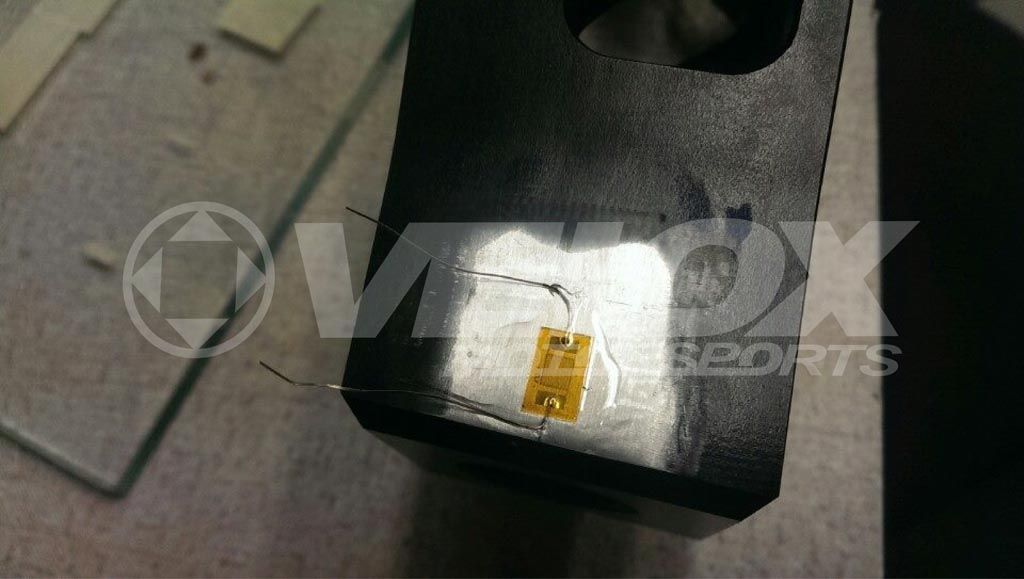
Strain Gauge being placed on the snout of LCA, this is a stress concentration for bending load and lateral load.

Strain Gauge being placed on the snout of LCA, this is a stress concentration for bending load and lateral load.
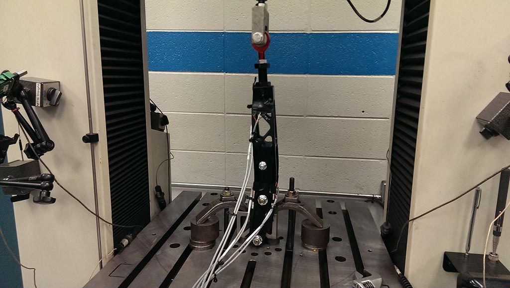
At this point, we needed to set up a test that was similar to the load an actual car may place on the LCA. Using some ingenuity, this was accomplished with some fixture plates we machined specifically for the project. Up first, was testing a single static load. We tested these at high forces to ensure the LCA could withstand a large impact. We tested both bump and lateral load at a load produced by a 4.5G acceleration. This is likely a load that the LCA will never see unless in an accident.

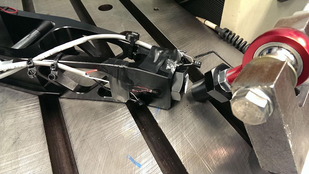
Statically loading the LCA with the force from a 5G acceleration load.

Statically loading the LCA with the force from a 4.5G bump acceleration.
Once the LCA passed the static tests, we moved onto longevity testing. To do this, we loaded the LCA in the same fashion above, with a little less load, repetitively. We tested at 3.7G and 10 hertz (10 loading events a second), which is a tad excessive but we could not wait all day to hit 50,000 cycles.
This was not without failures. We went through multiple adjusters due to the bending load subjected to them.
We are now working on producing these. Stayed tuned for more information. As always, if you have any questions or concerns, please comment below or send us an e-mail.

FT-86 Lower Control Arm Development