Designing products is what we do repeatedly at Verus Engineering; but, we have never really spoken about what goes into producing a new part, from start to finish, on the engineering side. We have seen multiple jaws drop, from customers to other businesses within the industry, when we mention how we have hundreds of drawings for every product we have ever produced! This is not always common knowledge, but proper engineering/manufacturing workflow dictates fully dimensioned components. Drawings ultimately dictate dimensional tolerances to keep a component within specification and fitting correctly repeatedly. In this blog post; we will be going through a product design cycle, from scanning to component design, to analysis, to revision, and finally to production drawings.
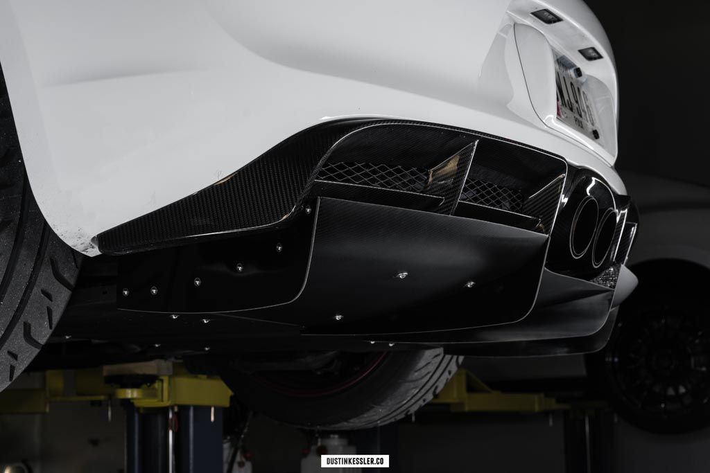
Scanning:
We start with scanning; which allows us to gather vehicle data necessary for the design of a new component. I will keep this section brief as we just released a blog/vlog post about scanning covering what scanning is and frequently asked questions. This can be read here: Scanning 101, FAQs, and Misconceptions and watched here: Vlog 007. These are great primers to how we use scan data and what it brings to the table.
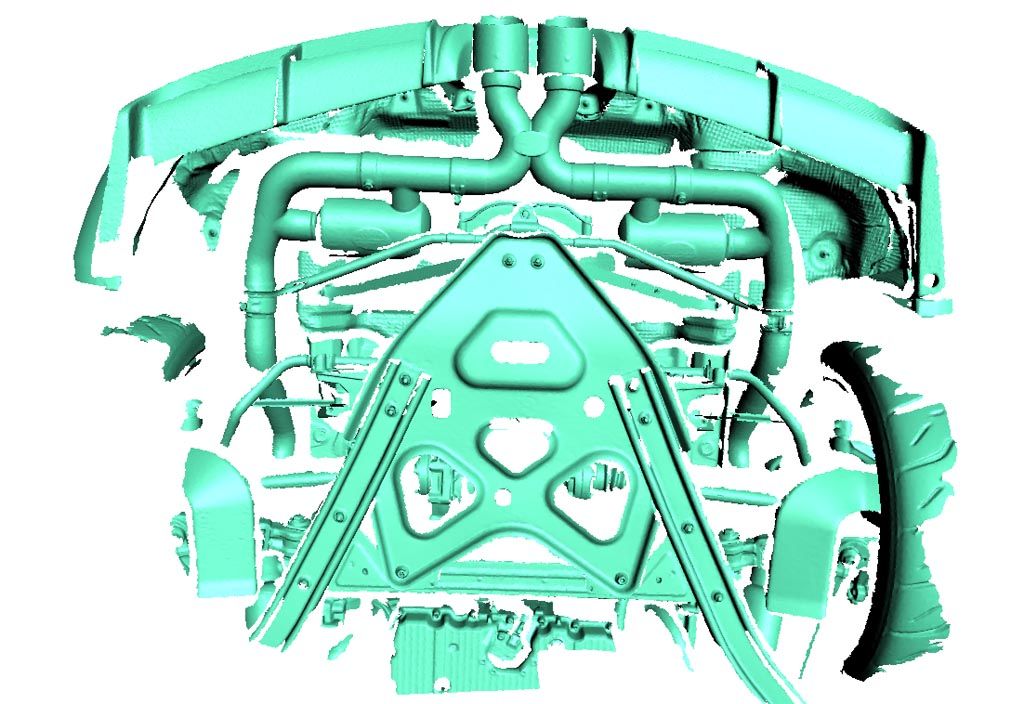
Designing:
Now, comes the fun part. Designing a component from scratch. Generally speaking, Paul will have ran a baseline CFD analysis on a stock bodied vehicle at this point. From this, we have a good idea of what to design. Taking into account a design that is functional, fits within the build volume, and is aesthetically pleasing, we will design an initial design concept. We pull on past knowledge/designs that performed well and do our best job to have the component attach to chassis locations that do not require any permanent damage to the vehicle.
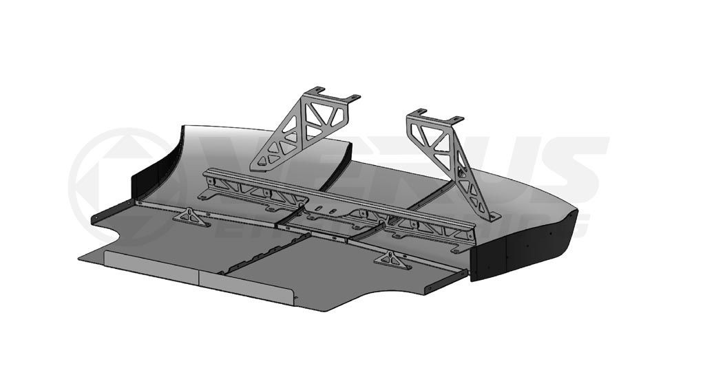
Analysis:
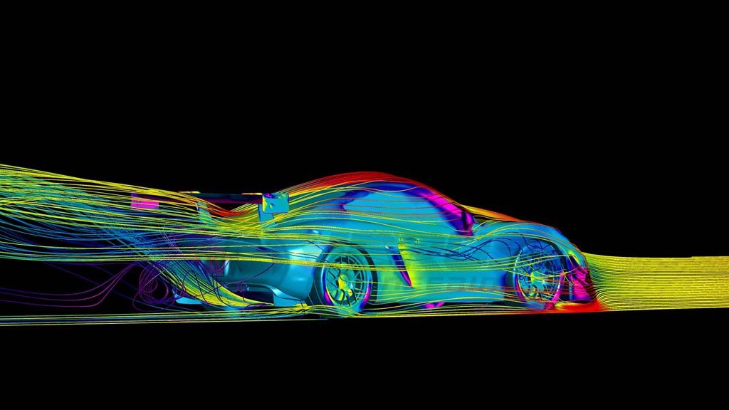
At this point, we add the designed component to the CFD model, remesh, and analyze the system again. All our analysis work is carried out in ANSYS, which is a state of the art CFD software. We will be creating blog posts in the future regarding our typical analysis approach, but we ensure every analysis has proper boundary conditions, rotating wheels, mesh quality, and turbulence model.
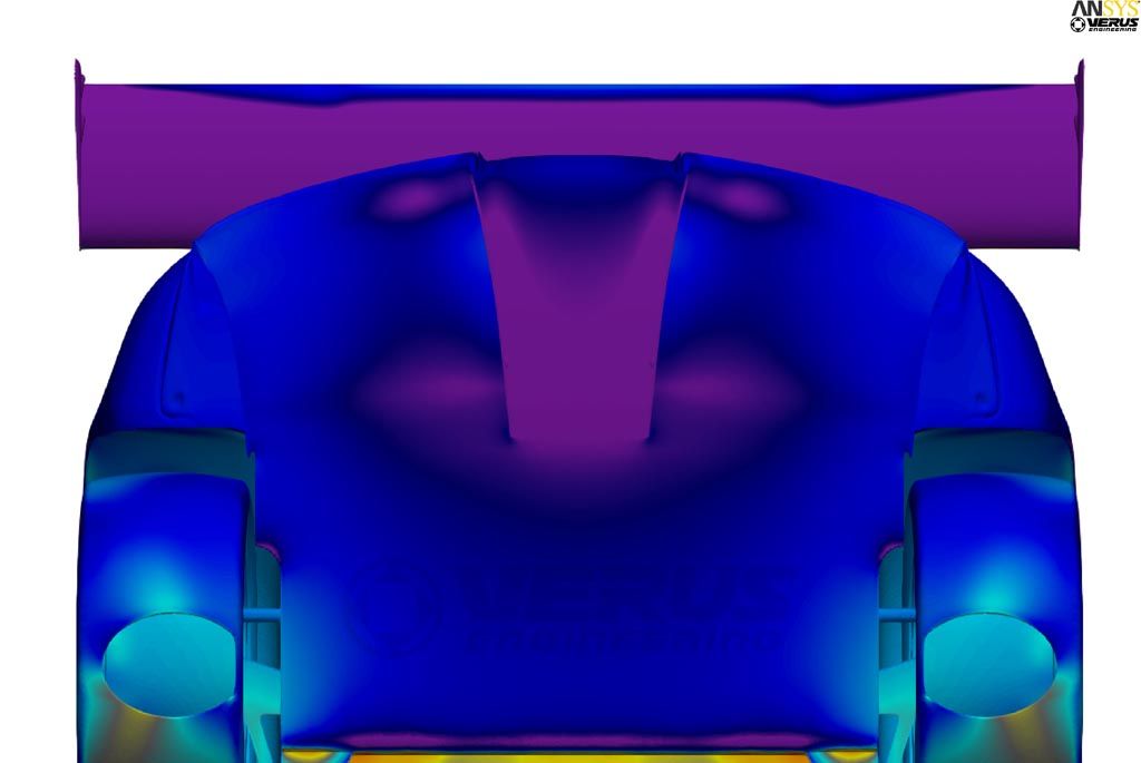
From the initial analysis, we look at both numerical data like Coefficient of lift, coefficient of drag, and aero balance and post-processing photos, typically pressure plots, velocity cut plots, LIC, etc. We then improve the components in an iterative process, or through the utilization of ANSYS’ optimization software; which improves the design for us! This is when we improve the functionality of the components we are going to be adding to the vehicle.
Production Design:
From the analysis, we have to take the improved design; and make it a manufacture-able model. The component in CFD is generally not a manufacture-able component as it is simplified for CFD. Typical simplifications involve holes and slots filled, multiple pieces fused to be one piece instead of a dozen, no hardware, non-standard thicknesses, etc. So from this simplified CFD model, we can create a CAD model that will ultimately become the physical part we will prototype and eventually produce.
Production Drawings:
Each component we design *needs* to have an associated 2D drawing. These are used by the manufacturer, with associated tolerances and dimensions, as a contract on what is to be built. These serve as quality control instruments as well; without drawings and tolerances, any part could technically be produced within spec. Machined components can have extremely tight tolerances; while bent sheet metal will require a looser tolerance due to the forming operation. Carbon will also have a bit of looser tolerance due to the fabrication nature of it. And castings/forgings will have fairly large tolerances due to the nature of molten metal being poured or hammered into shape.
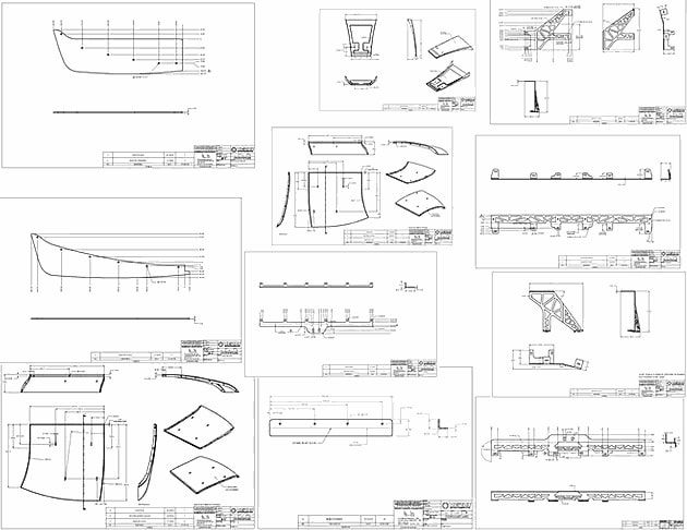
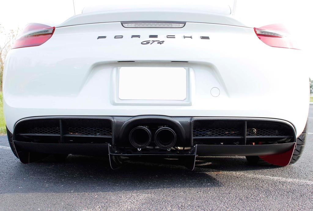
These drawings need to be fully dimensioned, showing bend lines, machine locations, hole sizes, overall sizes, etc. There is a specific science to engineering drawings, which I will not get into, but it takes years of learning how things are manufactured to learn best practices. This rear diffuser requires 11 drawings to be produced, 3 carbon fiber components, 2 plastic components, 5 sheet metal components, and 1 assembly drawing. Utilizing these drawings and associated 3D CAD, we can work with manufacturing companies to produce the components we have designed.
Conclusion:
We hope you learned a little about what goes into our design process here at Verus Engineering. We consider these fairly standard practices in the engineering world and something any manufacturing company should be doing.
Design Process 101