Purpose:
This document contains information and notes regarding the construction, features, and testing of the full brake kit designed and produced by Velox Motorsports for the FR-S, BRZ, and GT86
Design:
Starting from a clean slate with a solid idea in place, we wanted to design an OEM like brake cooling kit that maximizes cooling with as short of routing as possible. We also wanted to ensure it fit both big brake rotors and stock rotors alike. Doing our best to keep
Video Data:
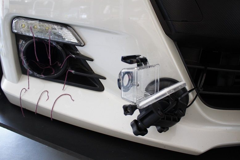
Using tuft testing we were able to visualize the flow and effectiveness of the inlet into the brake duct kit as well as the backing plate and carbon duct through the internal rotor vanes.
Thermal Imaging:
Using thermal imaging, we were able to test four conditions with the brake cooling kit. To keep the tests consistent, the passenger side had the full brake kit installed while the driver’s side was left OEM.
What is thermal imaging and how does it work?
Objects emit infrared energy based on a function of their temperature, also known as heat. This energy is referred to as the objects' heat signature. Generally, the hotter an object is, the more energy the object emits. A thermal imager (camera) is a heat sensor that is capable of detecting these differences in infrared energy or heat. These units collect the radiation from the viewing area and create electronic images based on this information and temperature differences. The unit we are using has a 330 degree C max temperature reading with an accuracy of +/- 1 degree C.
Testing Strategy:
Two control tests were mapped out that we believe accurately depicts the abilities of the duct kit in two severe cases and two cool down cases. Two speeds were tested, a 40 MPH low-speed test, and a 75 MPH high-speed test. This was to map out two different airflow rates, higher vehicle speeds translate to more airflow into the brake rotor via our kit. At each speed, we tested two cases, a severe braking case, and a cool down case. The severe braking case involved power braking with an engine load of 1.0 (constant load between the two tests) for 1 mile straight. The cooldown case involved driving the same road in the opposite direction with using
Please note the time and date stamp added from the thermal image camera, pictures were taken within 30 seconds of one another.
Thermal Image Data:
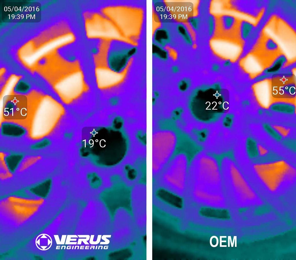
Thermal Image Data:
Figure 2: Control before the initial 40 MPH test, rotors are within 4 degrees C of one another.
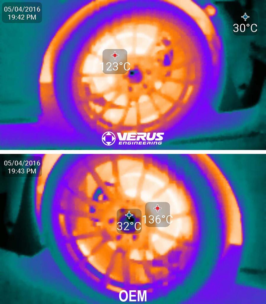
Hot readings directly after power braking for a mile.
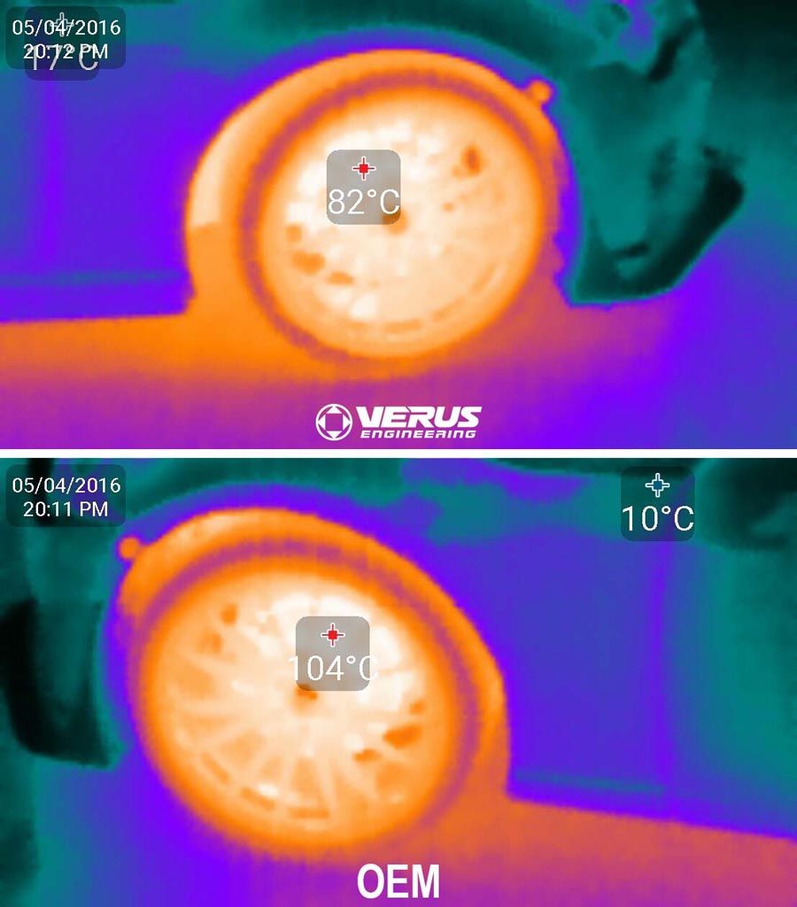
Cold readings directly after driving one mile at 40MPH with minimal brake use.
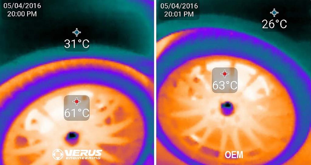
Control 2 showing rotors have leveled out in temperature after 12 minutes.
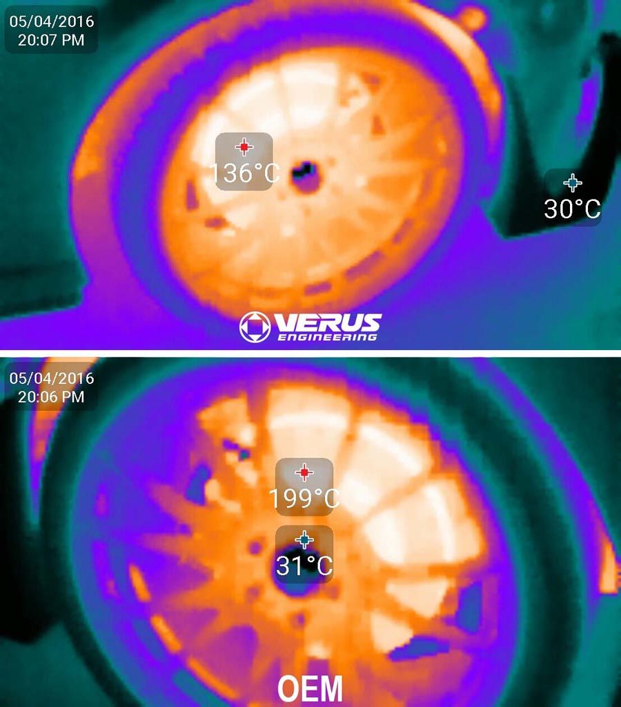
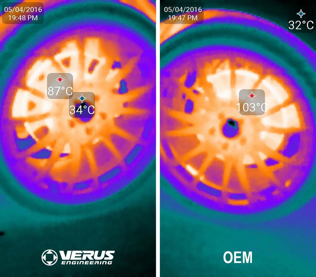
Hot readings directly after power braking at 75 MPH for 1 mile.
Numerical Data:
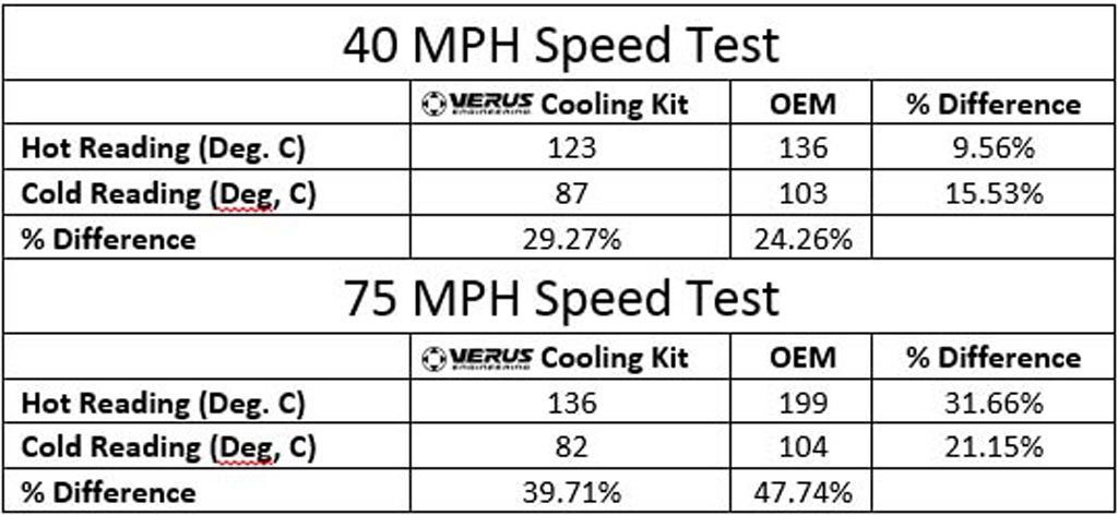
Numerical data from Thermal Images
Conclusion:
Via tuft testing and thermal image testing, it’s quite clear that the brake cooling kit is highly effective even when used with the OEM rotors which have quite small vanes when compared to those of big brake kits. Smaller vanes will reduce flow and cooling due to the smaller vane size.
With the brake cooling kit, the rotors remained much cooler directly after applying the brakes as well as after a short drive without using the brakes. It is also apparent that at high rates of speed, the brake cooling kit does significantly more than at lower speeds. This makes a lot of sense as the kit works by using frontal ambient air and funneling it into the center of the rotor. At higher speeds, pressure and flow rates are greater than at low speeds.
We have heard reports back from customers tracking their cars having reduced brake fade, reduced rotor cracking, improved pad wear, and reduced brake fluid boiling. As a result, this is a great kit to help keep brake components at an appropriate temperature during competition and/or track days.
Brake Cooling Kit Functionality and Testing Data