Purpose:
This document contains diagrams, information, and notes regarding the CFD analysis of the front splitter endplates for the FR-S and BRZ.
Design:
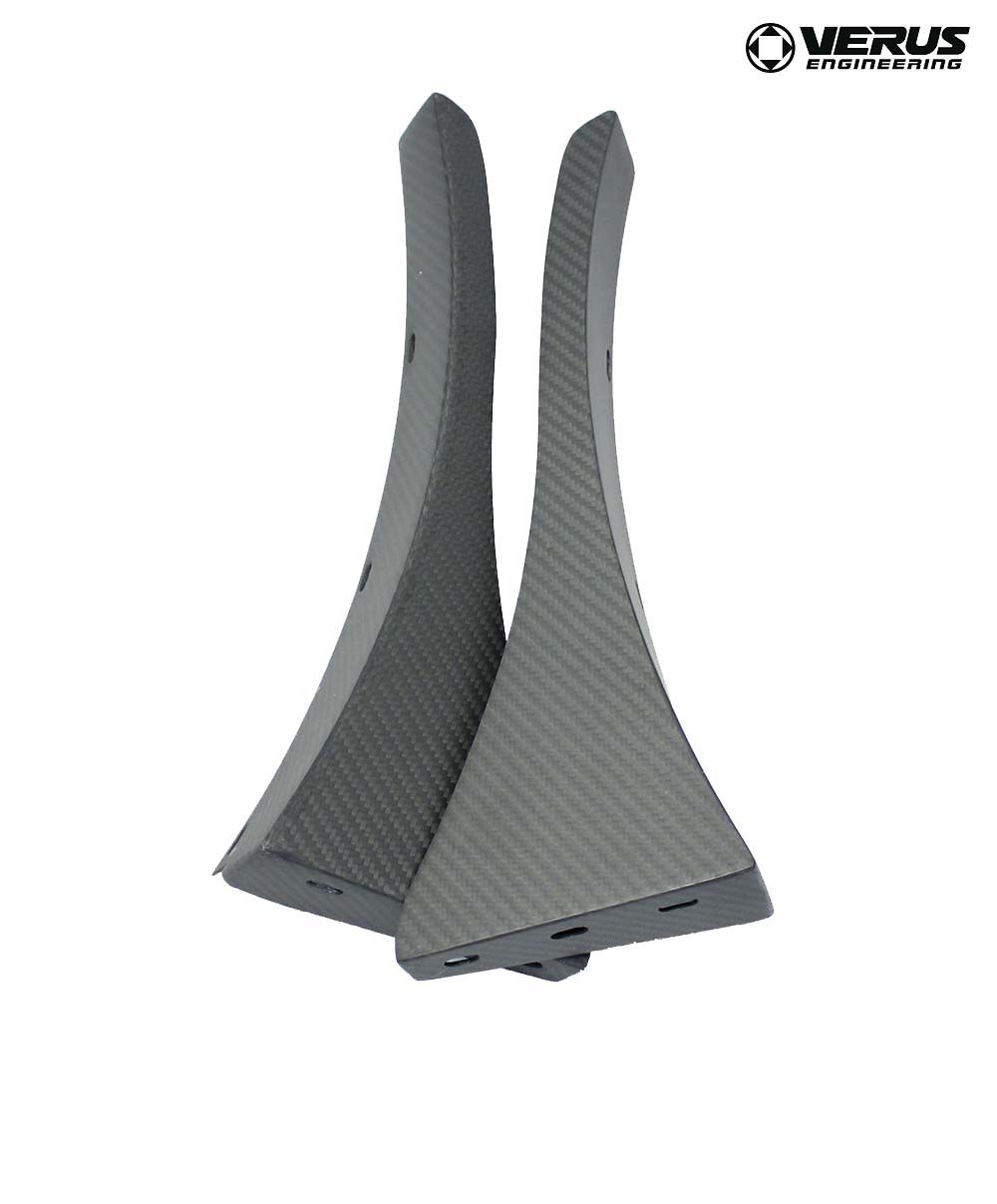
The front splitter endplates were designed to increase front-end downforce of the vehicle for improved performance at high rates of speed. By creating a high-pressure pocket of air above the splitter and in front of the front wheels, we are able to increase front-end downforce. By reducing the airflow that hits the wheel head-on, we also reduce the airflow into the wheel well and thus lift generated in the wheel well.
Like all of our analysis before, each analysis was done using a half-car analysis since no yaw testing was completed. This is done using symmetry down the centerline of the car. Significantly less computational processing power is necessary when using a half-car model and was the reason behind this analysis approach. The meshing of the car is done using first a surface mesh and then volume mesh. To find a suitable mesh size for the analysis, a grid convergence study was done. A volume mesh count of 10 million cells was considered within the room for accuracy using mesh sensitivity analysis.
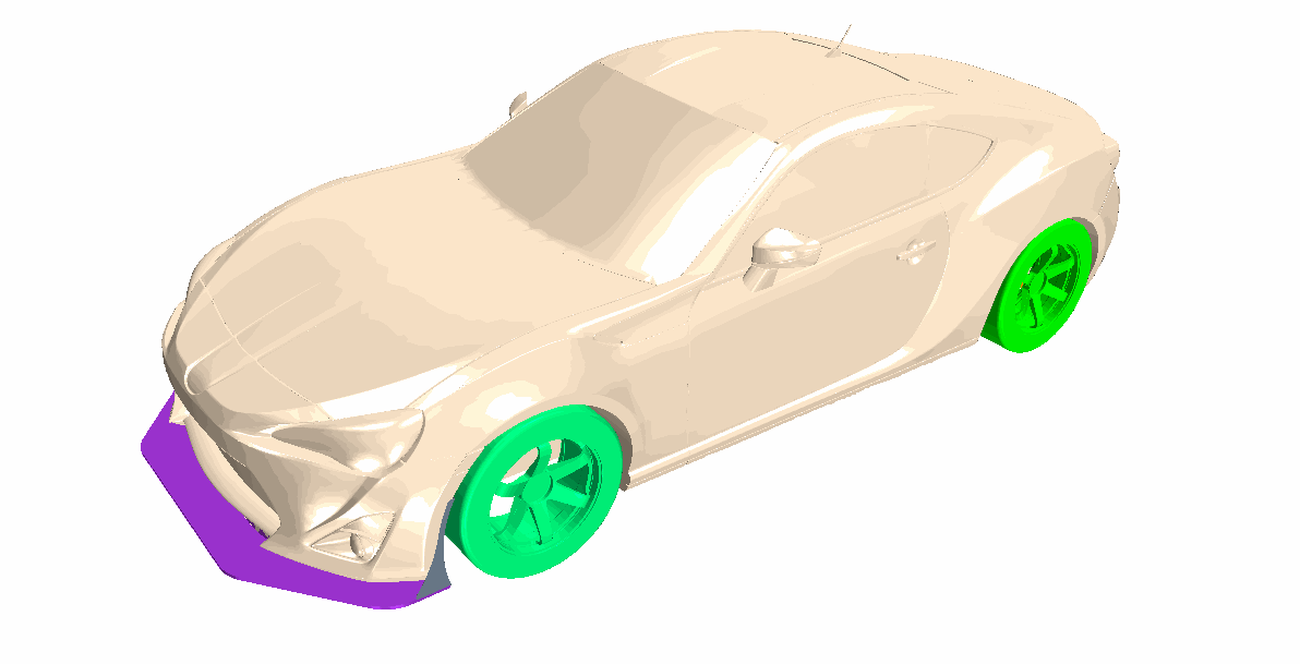
The Vehicle with Components in CFD Software
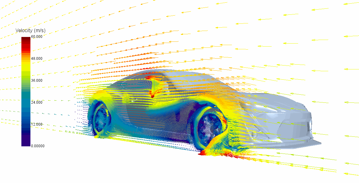
Vector Plot of Front Splitter Winglet

Streamline Plot of Front Splitter Winglet Test
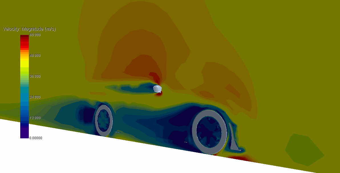
Scalar Plot of Front Splitter Endplate CFD Analysis
Numerical Data:
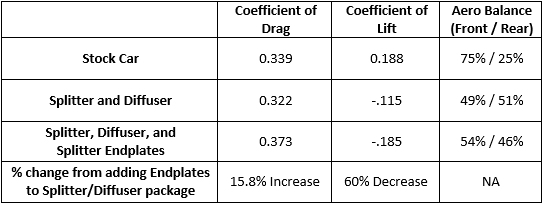
The front splitter endplates increase downforce and drag according to our CFD analysis. The additional front downforce comes with a penalty of increased drag, however, the l/d (lift over drag ratio) for this component is favorable. To put in another way, the amount of downforce this part produces is significant compared to the amount of drag increase.
Conclusion:
At a mere 100 MPH, these two pieces add an expected 40 lbs of downforce to the car. These can be used to help balance out a rear wing or allow the end-user to run a bit more wing angle for faster times.
As we have said before, real-world benefits may differ as this is computational analysis. Something as simple as ride height or wheel choice can vary results, as well as various other aspects. Real-world results could be better or worse than what is shown above. Keep in mind we did NOT vary any of these aspects and kept it a very simple A to B comparison with the results outlined above.
Very few companies perform CFD or wind tunnel analysis on any of their aerodynamic pieces. As a consumer, you can rest assured that you are receiving a quality component with engineering analysis and theory backed components that perform as well as they look.
Front Splitter Endplate CFD Analysis