Diffuser Trailing Edge Analysis - Ahmed Model Testing

Testing on a Generic Car Model
June 3, 2016 by
Verus Engineering Ahmed Model Diffuser Testing CFD

Purpose:
Our diffuser's rear up-turned lip is a bit unconventional and has some skepticism associated with it. The main goal of this analysis is to see how adding a diffuser and then a radius at the end of the diffuser can increase the efficiency of a vehicle.

Verus Engineering Ahmed Model Diffuser Testing CFD Mesh

Meshing and Solving:
ANSYS provides the best engineering analysis software available, period. With fluid systems, structural systems, and Multiphysics, just to name a few, they have analysis software for nearly any and every application possible. ANSYS is linked with the biggest names in nearly any industry that requires engineering.

Why was the Ahmed Model Chosen?

The Ahmed model is a universal benchmark used in the automotive field for validating simulation tools. It is also a great model to use for general changes to analyze the effect on a basic vehicle system. Effects on this model likely can transfer to other vehicles, but as always, we recommend and will always perform analysis on vehicle-specific units as each case can vary.

Standard Ahmed Model CFD:

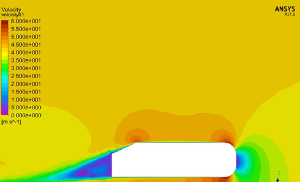
Being that this is an A to B to C comparison, we, of course, have to start with the standard Ahmed model.  CFD photos of this are shown below.  We took this time to compare the standard Ahmed results to published results as well.
Verus Engineering Ahmed Model Diffuser Testing CFD Velocity Plot

Diffuser Ahmed Models CFD:

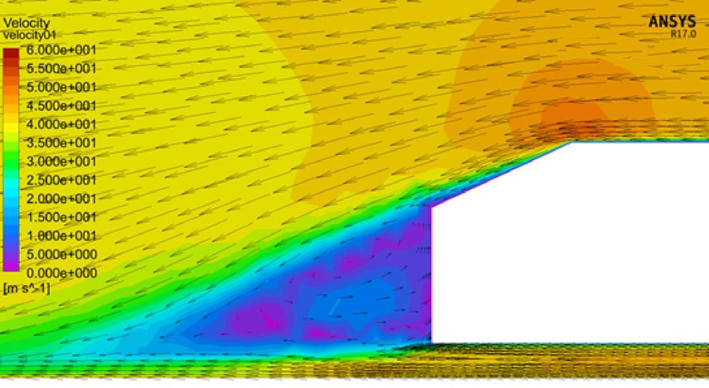
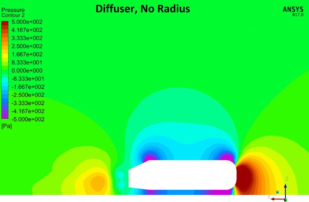
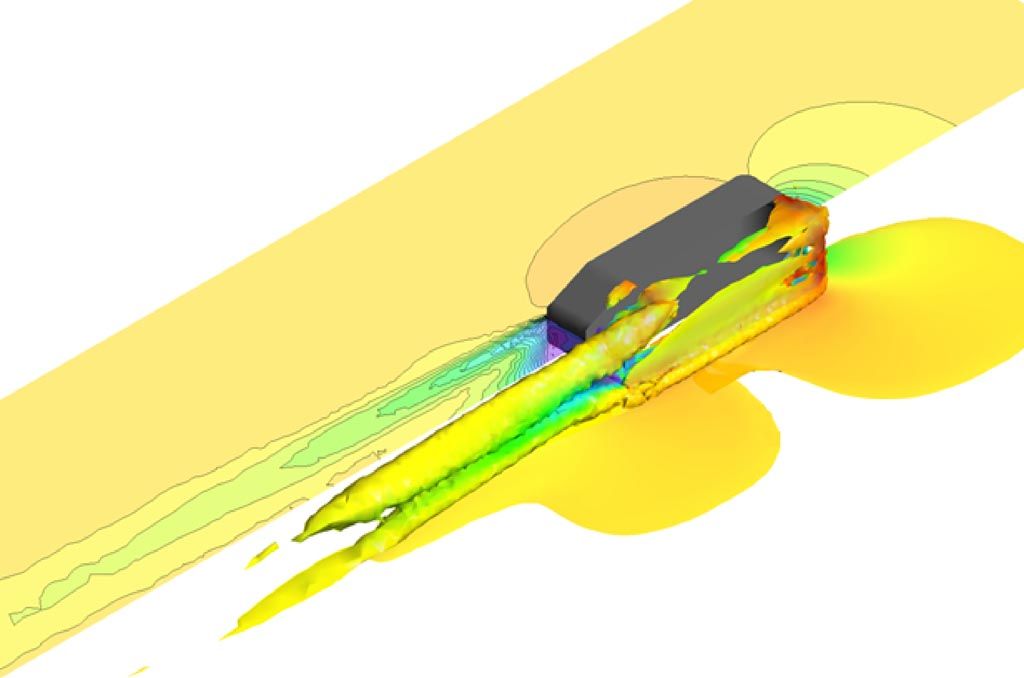
We added a diffuser by removing material from the Ahmed model and reran our CFD test.  We then added a radius to the rear-most portion of the diffuser to represent a similar up-turned lip to our diffusers.  Below are some of the CFD photos.

Velocity Contour Plot:
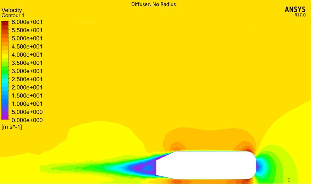
Verus Engineering Ahmed Model Diffuser Testing CFD Velocity Plot

Pressure Contour Plots

Verus Engineering Ahmed Model Diffuser Testing Pressure Plot

Diffuser Models Numerical Data:

The numerical data speaks volumes. The diffuser with a radius at the end is more efficient. Not only does the radius diffuser make more downforce, but it has less drag. The plot is a pressure plot along the Ahmed body. The red (radius diffuser) can be seen to have lower pressure points across the surface of the body.
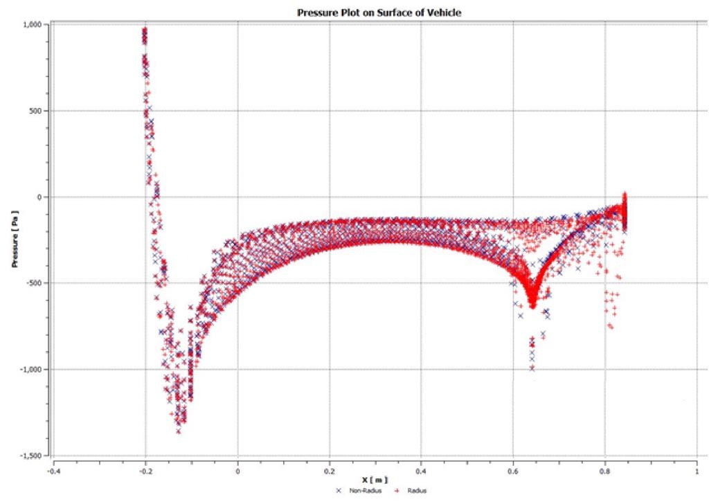
Verus Engineering Ahmed Model Diffuser Testing Surface Pressure
Verus Engineering Ahmed Model Diffuser Testing CFD Numerical Data

Conclusion:

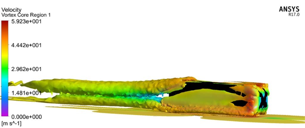
For this analysis, the radius on the rear of the diffuser makes the vehicle more efficient. This might not always be the case, but this analysis does indicate that the radius on the rear diffuser is not only structurally beneficial but aerodynamically as well.  Regardless, we always suggest that all setups should be analyzed and tested before implementation.  This is why we CFD test every model and every diffuser we design for optimization.
Verus Engineering Ahmed Model Diffuser Testing CFD
June 3, 2016
Share this post
Tags
{ "@context": "https://schema.org", "@type": "VideoObject", "name": "What Do Front Splitters Actually Do?", "description": "Eric from Verus Engineering explains the function and benefits of front splitters in automotive design, detailing how they produce downforce and improve vehicle performance.", "thumbnailUrl": "https://i.ytimg.com/vi/PYJYN_s9Uqk/hqdefault.jpg", "uploadDate": "2024-03-09", "duration": "PT9M49S", "publisher": { "@type": "Organization", "name": "Verus Engineering", "logo": { "@type": "ImageObject", "url": "https://www.verus-engineering.com/logo.png" } }, "contentUrl": "https://www.youtube.com/watch?v=PYJYN_s9Uqk", "embedUrl": "https://www.youtube.com/embed/PYJYN_s9Uqk" }